Tektronix 492 Spectrum Analyser
Spectrum analysers are devices for measuring the frequency components of a radio signal (RF). The Tek 492 is a relatively old model (from the 1980’s), but it has pretty decent specifications, even today.

How it Works
This spectrum analyser uses a swept heterodyning technique. It takes the input RF signal and mixes it with a reference signal. The mixing of these two signals essentially creates a lower-frequency output signal (since the two inputs beat against one-another) which is then fed into a bandpass filter to be converted to a signal level for the current reference oscillator frequency. Sweeping the reference signal frequency allows a large range of the RF spectrum to be measured. The instrument that I have is able to measure from 50kHz to 20GHz, which is good performance even with today’s technology.
Fault Finding
The instrument that I’ve got was being disposed of as non-working, and did not show any signal on the CRT. When it was powered on, the keys lit up, and changed state whilst it booted which gave me hope that it wasn’t badly damaged. Knowing that many failures in old electronics are related to faulty electrolytic capacitors, I thought that it would be interesting to see if it was repairable.
When I first opened the case (which is really easy – just four screws on the back), I noticed that there are a row of test points for most of the voltage rails next to the CRT. A quick probe with my multimeter revealed that the +15V rail was showing nothing, the -7V rail was reading +17V and the 300V and 100V rails were out of specification.
Test Point Measured Value +300 +259 +100 +141 +17 +17 +15 +0 +5 +4
-7 +17 -5 -5 -15 -15
+9 +9
The next step was to check the voltages at the power supply. The PSU on this model is a separate unit that connects onto the edge of the main motherboard via a card-edge connector. It’s just a case of removing a few screws and the PSU can be separated and tested independently. I found that the fuse on the -7V rail had blown, which made it odd that the test point for that rail was reading +17V. This implied that the fault was downstream of the PSU since voltage would not be able to leave the PSU through the blown fuse. I connected the PSU to power, and found that the rail was indeed delivering -7V when not connected to the rest of the instrument.
Fortunately, the Tek service manuals are available online so I was able to look at the circuits on each of the boards to try to see what the cause of the blown fuse and incorrect voltage reading could be. I discovered that the 15V rail was not fused on the PSU, and was derived from the -7V rail (as part of its linear regulator), so it was possible that the two faults were related. I began to disconnect the various cards within the instrument to see whether the voltage on the test points would return to their expected values. Removing the SPAN ATTEN board caused the 15V test point to return to normal.
Looking at the circuit diagram for the SPAN ATTEN board, I found that there were a number of capacitors that filter the power supply on the 15V rail. Two of them (which were placed in parallel) measured short circuit. I cut the leg on one of them and found that it (C5038) was short, the other was not. The first fault is found.
From the service manual, I discovered that the -7v and +17V rails are used together to generate 24V in a number of the modules within the analyser, so the failure of the fuse would possibly explain the 17V on the -7V test point. Notably, there is a crystal oscillator in an oven that uses 24V to drive a resistive heater for temperature control. My theory was that this resisitor heater was the connection between -7 and +17 – removing the heater connection and powering on the analyser confirmed this fact. I replaced the fuse and powered the analyser on.
What had happened
The fault was caused by a single capacitor on the Span Attenuator board drying out and going short-circuit. This caused a large draw on the 15V line, which caused the 15V linear regulator to draw excessive current from the -7V line within the power supply. This large current draw blew the -7V fuse, causing loss of the -7V line and also loss of the 15V supply. Without the 15V supply, the scanning circuitry for the CRT wouldn’t run, which made the analyser appear to have failed.
How I fixed it
I replaced the fuse on the -7V line with a new one, and replaced the capacitors on the Span Attenuator board. Fortunately, the Tek service manual give exact part numbers of all components within the unit, so it’s relatively simple to find parts with the correct specification.
All working
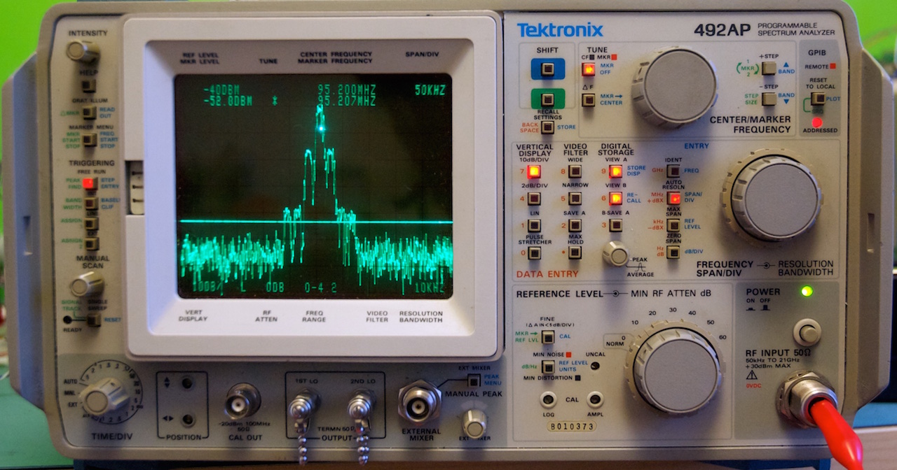
The analyser now appears to be working correctly; here’s the local radio station at 50kHz resolution.