Arduino Controlled Soldering Station
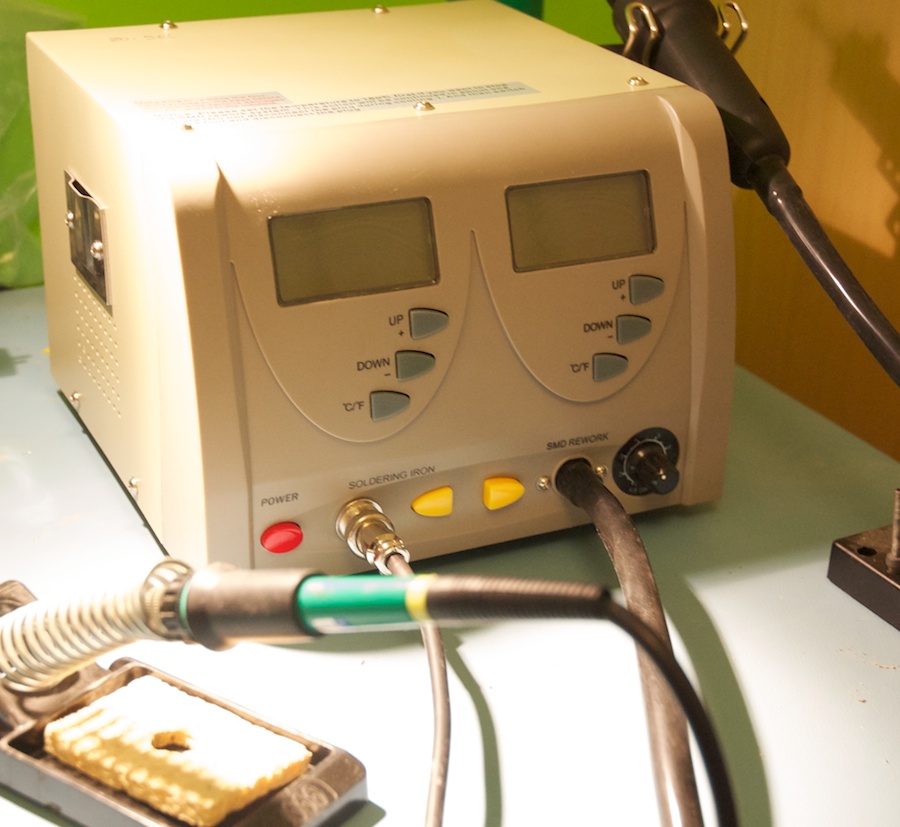
I replaced the faulty controller in my soldering station with an Arduino. The soldering station is a combined iron and hot-air lance and is branded as a Duratool ZD-912. I got it from Farnell, but Maplin in the UK stock the little brother rebadged as their ZD-916. I believe that the original manufacturer is Zhong-Di, who are an OEM soldering tool manufacturer.
What’s Wrong with it
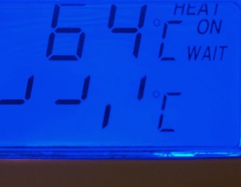
The station unexpectedly stopped working recently and I was no longer able to change the set temperature on the controller. Oddly, the temperature control itself still seemed to be working since the temperature is regulated to the last set-point (330ºC) and the read-out displays the current temperature.
I first assumed that there was some issue with the set-buttons, but these appear to be working – the C/F button allows the display to be changed into foreign temperature units, and the + and - buttons seem to change the voltage state on the pins internally when they’re pressed. Since the set-point readout on the display apeared faulty, my next assumption was that the microcontroller had become corrupt (since the station seemed to fail when I turned it on). This doesn’t really make sense either because the PWM/PID still appears to work on the temperature control (see the photo below). It might somehow be the LCD controller, or something else. No idea. No matter: hack time.
Planned Solution
Since the temperature control is working, I reasoned that the temperature measurement was still fine. In this iron, the temperature measurement is done using a thermocouple (you can tell this because the resistance across the pins in the iron is essentially zero, and there’s a small voltage created across two of them when the iron’s warm).
I decided that the solution is to hack into the control PCB and replace the electronics that’s not working with some that is. In this case, I chose an Arduino Nano that I’ve got in stock.
The first step was to work out how to measure the temperature of the tip. Fortunately, the temperature measurement appears to be working fine in the main iron controller, so I reasoned that the temperature measurement system was ok. The input from the thermocouple is soldered onto the PCB and is filtered with some sort of RC network (I didn’t bother to try and trace it all out) and them amplified with a TL431 op-amp. The output from the op-amp is then passed through a trimmer resistor (to allow calibration of the temperature measurement) and passed to an analogue input on the Silabs 8051C310F microprocessor that controls the whole iron.
The microprocessor then compares whether the iron needs to be heated and uses a PID control loop to maintain the temperature set-point. The microcontroller then modulates the power to the iron via a cable to a power MOSFET on a separate board.
My hack will replace this part of the circuit with an Arduino to read the analogue value from the thermocouple and then drive the heater control MOSFET to get the iron to the setpoint.
Hardware Hack
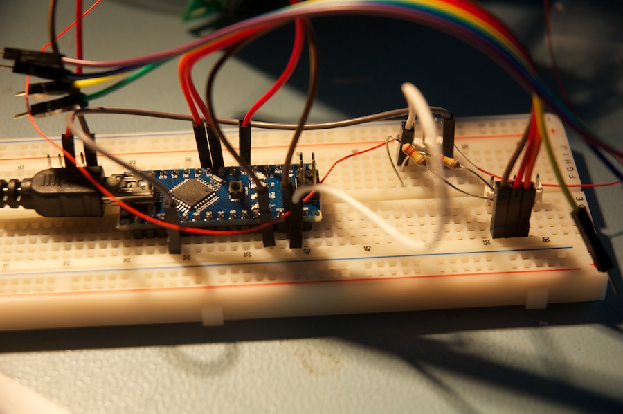
I made a small circuitboard to carry an Arduino Nano and allow me to wire the pins from the switches etc. into the Arduino. The board has a couple of headers to connect to the plugs for the FET and the front panel switches, a couple of resistors to pull the switch input lines low (for voltage sensing), and that’s about it.
Whilst I was connecting the board into the original PCB on the iron, I noticed that the TO92 package LM7805 regulator that drops 16.2V from the bridge rectifier/transformer to the 5V for the control electronics was very hot. Since this is not a great thing to expose small regulators to, I swapped it out for a larger 7805 in a TO220 package, which can handle the load more easily.

Software
The software is really simple. I used the Arduino PID library and based my code on the example there. It’s available on github, and is shown below.
PID Tuning
The PID control variables could probably benefit from some tuning, but they’re close enough to prevent too much overshoot, and the FET doesn’t seem to be working crazy-hard once the iron’s up to temperature so I’m happy enough with them.
/********************************************************
 * PID Soldering Iron Control
 * Reading analog input 0 to control analog PWM output 3
 * Based on PID_Basic example from the PID Library
 * Tim Stephens, 6 April 2014.
 *
 *
 * Requirements:
 * PID Library https://github.com/br3ttb/Arduino-PID-Library/
 ********************************************************/

#include <PID_v1.h>

//Define Variables we'll be connecting to
double Setpoint, Input, Output;
//These setpoints roughly correspond to 260, 295, 310, 330, 350C
//Based on one experiment cooling down...
//Your Iron may Vary

int setpoints[] = {70, 200, 250, 340, 450};
int currentSetpoint = 0; //Always start at the coolest temperature.
int upButton = 5;
int downButton = 6;

//Specify the links and initial tuning parameters
PID myPID(&Input, &Output, &Setpoint,1,0.1,0.5, DIRECT);

void setup()
{
  pinMode(upButton, INPUT);
  pinMode(downButton, INPUT);
  Serial.begin(9600);
  //initialize the variables we're linked to
  Input = analogRead(0);
  Setpoint = setpoints[currentSetpoint];

  //turn the PID on
  myPID.SetMode(AUTOMATIC);
}

void loop()
{
  Input = analogRead(0);

  myPID.Compute();
  Serial.print("Setpoint = ");
  Serial.print(Setpoint, DEC);
  Serial.print(" Temp Reading = ");
  Serial.print(Input, DEC);
  Serial.print(" Output PWNM Value");
  Serial.println(Output, DEC);
  analogWrite(3,Output);
  delay(200);


  //Now to set an appropriate temperature setpoint
  //(and make sure we stay within the bounds of the array)
  if(digitalRead(5)==1) {
    currentSetpoint++;
    if(currentSetpoint > 4) {
        currentSetpoint=4;
    }
  } else if (digitalRead(6) == 1) {
    currentSetpoint--;
    if(currentSetpoint < 0) {
        currentSetpoint=0;
    }
  }

  Setpoint = setpoints[currentSetpoint];
}
Caveats
There are a number of caveats with this code:
1) It doesn’t show the setpoint on the display on the front of the soldering station. 2) The number of setpoints are limited (I could use more, but without a display, it doesn’t seem worth it). 3) The PWM to drive the MOSFET is at the Arduino’s default 490Hz, which is probably way too fast for this application. Switching the FET at this rate will likely cause it to get quite hot, so it might not live forever. Fortunately it’s on a big heatsink and was previously only driven with 2.5v (according to my multimeter), so it should be OK with the 5V I’m pushing into it now. 4) No warranty. If something breaks, you’re on your own.