Garage Door Alarm
In our house, we have an electric garage door. Unfortunately, the radio control for the electric opener doesn’t work. Initially, we worked around this by going into the garage through the side door, but this became old really quickly. I realised that I could tap into the existing connection for the internal opener (a bell-push mounted on the back wall of the garage) by running a cable into the house and fitting a second push-button. However, I also realised that we wouldn’t have the discipline to remember to close the door when we got home sometimes (especially since we’d forgotten a few times by that point). My first thought was that some sort of alarm that reminded me when the door had been left open for a short while would be super-helpful since it would stop us leaving our bikes exposed overnight.
The obvious candidate was to use a pic microcontroller to sound a beeper, and it just happened that I had a most of the components I needed in my parts bin already, including a pic18f2550, a piezo beeper and a pcb ready for a pic with plenty of io connections on it.
Because I didn’t want to chew power monitoring the door, I decided that I wanted the circuit to be battery powered rather than using a wall adaptor, but this introduced another issue: how to make it last for ages on a single battery. Since the door is closed for the majority of the time, it’s hopefully clear that the cleverest thing to do is switch the whole thing off when the door isn’t opened. To do this, I employed a normally closed reed switch. I had a normally open reed switch door sensor from an old burglar alarm installation that I fitted years ago, so I purchased an nc switch and transplanted it into the casing and fitted this to the door.
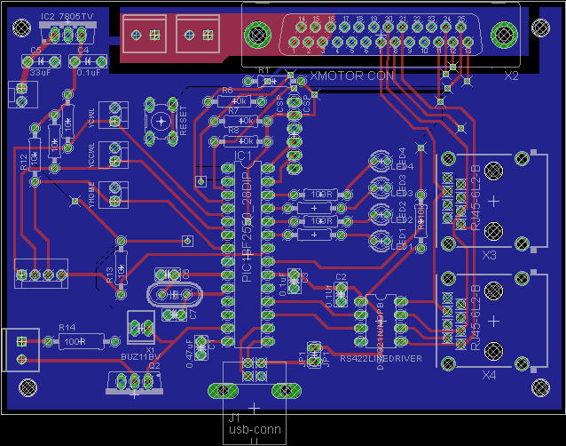
Then, I drilled a hole through wall between the garage and the house to let me fit a wire through. The wiring is super simple. A 2 core cable is connected from the bypass terminals on the back of the door closer at the roof of the garage to a junction box near the hole in the wall. Another cable connects to the door switch. A second 4 core cable connects from the junction box through the wall to a case that’s mounted on the wall in the hall. The circuit diagram is shown in the picture below.
Parts List
The parts include
- PIC18F2550
- PP3 Battery
- Printed Circuit Board
- Piezo Buzzer
How it works
When the door is closed, the reed switch is open and the power is turned off. When the door is opened by pressing the button on the control panel, it closes the reed switch and the pic starts a timer. The timer counts up for 5 minutes, and then starts a beeper. At any time you can press the silence button, which stops the timer from counting and puts the pic to sleep to save power. I employed a couple of other tricks to try and save battery by only testing the state of the silence switch once every half a second. The pic also controls the state of the pull-up resistor on the silence switch so it also de-energises the pull-up voltage when the state of the switch isn’t being tested.
The firmware is written in c18, using the microchip c compiler and is shown below.
Since I installed this system, it’s been activated about once per week, which means that the number of times we’ve accidentally left our garage door open overnight has been significantly reduced. It goes without saying that I’m very pleased with the performance of this system.
//Test file containing something to toggle RA0
//Garage door monitoring beeper system.
#include <stdio.h>
#include <delays.h>
#include "timers.h"
#include <stdlib.h>
#include <pwm.h>
#include <adc.h>

#pragma config FOSC = INTOSCIO_EC //internal oscillator, running at 4MHz
#pragma config WDT = OFF //no watchdog
#pragma config VREGEN = OFF //disable USB regulator
#pragma config LPT1OSC = ON //low power timer 1
#pragma config PBADEN = OFF //disable Analogue input on RB0-4


//config
 	#define mLED_1              LATBbits.LATB2
    #define SILENCE_PULLUP      LATBbits.LATB3
	#define toggleStatus()		mLED_1=!mLED_1;
	#define TRISA &= 0b00010000  //set only
	#define SILENCE_BUTTON		PORTBbits.RB4

void silenceAlarm(void);
void soundAlarm(void);
int countdown;  //global timer counter.
int delay = 0x2FF;  //countdown delay value - timed  to be ~5minutes in debug mode.

#pragma code
#pragma interrupt InterruptHandlerLow

void InterruptHandlerLow()
{
	if (INTCONbits.TMR0IF==1)
	{
		//toggleStatus();
		countdown++;//increment timer

		INTCONbits.TMR0IF=0; //clear interrupt flag
		SILENCE_PULLUP = 1; //Put voltage on the pull-up so that we can test its state
		if(!SILENCE_BUTTON){
			silenceAlarm();
		}
		SILENCE_PULLUP = 0; //Turn off pull-up
		if(countdown > delay) {
			soundAlarm();
		}

		WriteTimer0(0); //reset timer
		Delay10KTCYx(10);
		OSCCONbits.IDLEN=1;
		Sleep();
	}

}


void main()
{
	//int frequency = 0xa0;
	unsigned char config1=0x00;
	unsigned char config2=0x00;
	// setup IO
	LATB &= 0x00;
	TRISB &=0x10; //only RB4 is an input.
	PORTA &= 0;  //make sure that port  A is driven low.
	//interrupts
	INTCON=0; //disable all interrupts.
	INTCONbits.GIE=1;  //enable global interrupts.
	INTCONbits.TMR0IE=1;  //enable TMR0 overflow interrupt.

	countdown = 0;

	config2= T2_PS_1_1 & TIMER_INT_OFF;
	OpenTimer2(config2);
	SetDCPWM1(100);  //Set PWM duty-cycle to 50%
	OpenPWM1(57);
	Delay100TCYx(128);
	ClosePWM1();  //make sure no beeper is on.
	//SILENCE_PULLUP = 1; //turn on pullup for Silence button.

	config1= TIMER_INT_ON & T0_8BIT & T0_SOURCE_INT & T0_PS_1_64;
	WriteTimer0(0); //reset timer
	OpenTimer0(config1);


	while(1);
	{


	OSCCONbits.IDLEN=1;
	Sleep();
	}
}


void silenceAlarm(void)
{
	int i;
	for(i=0;i<2;i++)
	{
		OpenPWM1(57);  //At 4MHz, this should give ~4.6kHz which is natural frequency of piezo beeper
		Delay1KTCYx(64);
		ClosePWM1();
		Delay1KTCYx(64);
	}

	ClosePWM1();
	SILENCE_PULLUP=0;
	mLED_1=0;

	while(1) //minimise power drain.
	{
		OSCCONbits.IDLEN=0; //make sure it actually sleeps, rather than idles
		Sleep();
	}
}

void soundAlarm(void)
{
	while(1)
	{
		SILENCE_PULLUP = 1;
		if(!SILENCE_BUTTON)
		{
			silenceAlarm();
		}
		SILENCE_PULLUP = 0;
		OpenPWM1(57);  //At 4MHz, this should give ~4.6kHz which is natural frequency of piezo beeper
		Delay1KTCYx(128);
		ClosePWM1();
		SILENCE_PULLUP = 1; //silence the alarm once it's going off.
		if(!SILENCE_BUTTON)
		{
			silenceAlarm();
		}
		SILENCE_PULLUP = 0;
		Delay1KTCYx(128);
	}
}