SLT Instruments
Together with two friends, I produced an Elispot plate reader for immunological plate screening. Elispot is a high-sensitivity technique for screening cellular assays for particular cell types and diseases. The work was formed in two parts.
Technique
The Elispot technique uses standard 96 well assay plates (the type that you see people in white coats moving fluids about in whenever the TV news wants to talk about science or genetics). Cellular samples are put into these small wells, which are about 6mm in diameter and then stained with a reagent that highlights whatever the cell of interest is. Next, the cells are washed away leaving the stain behind. The size and intensity of the remaining stained slot is used to determine the quantity of cells of interest in the sample. The Elispot plate reader is essentially an x-y table with a camera and lighting system mounted above it. The table moves the plate so that it’s underneath the camera, which snaps a picture. This process is repeated until the whole plate has been imaged.
Existing Systems
A number of systems already existed on the market, but these were slow and had cumbersome software to control them. Together with a software developer, we designed a system that was faster than competing products and features a more user-friendly software interface. I was solely responsible for developing the hardware parts of the spot-reader. This entailed designing all the metalwork for the motion-control system, camera mounting, camera optics and illumination system.

Motion Control Hardware
I decided to design a bespoke motion control system rather than rely on one that was off-the-shelf because this guaranteed that we could have the most compact footprint and stack-height. The motion slides were an off-the-shelf part that greatly simplified design and mounting. I used a reinforced rubber timing belt to drive the stages from the motors because this produced backlash-free motion. The motor themselves were massively over-specified to ensure that they would not skip or slip, and contained all of their drive electronics. This meant that they did not require a special driver circuit and could be moved synchronously. Motor control was achieved by sending serial commands to the motor via an RS422 bus. Up to 26 motors can be connected to the bus, which left significant head-room for later expansion.
Electronics
I designed, manufactured and coded a pic-based circuit board to allow the system control to be connected via USB to the system computer, and to translate commands between the motors and the pc software. The advantage of using a translation step is that the computer does not need to know about the motor’s status (they won’t accept new move commands whilst they are moving) and does not need the know the command protocol. This means that it will be possible to replace the motors at a later stage with a different controller without having to recode the pc software interface.
I designed the circuit based on a PIC18f2550 microcontroller, which has a built-in USB controller. This then connects to an RS422 transceiver to communicate with the motors. I used EAGLE PCB software to design the circuit and lay out the printed circuit board. The board themselves were manufactured with pcbpool, an online circuit board manufacturer. Once the board was complete, I assembled the components and tested the operation.
*Picture of pcb
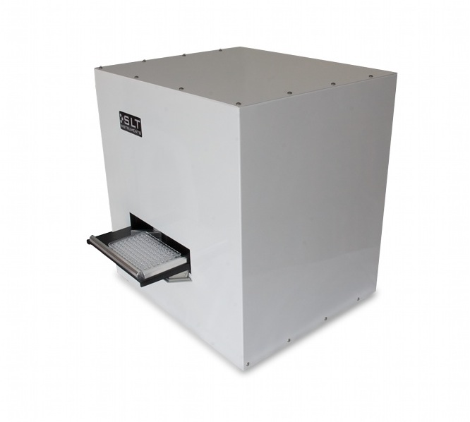
Hardware
The case was formed with 1mm sheet steel since this is easy to work with for small volume manufacturer and engineering firms. I created a 3d model of the case, and then produced engineering drawings for the engineering companies to work from. The mechanics of the x-y table were formed from machined aluminium, which I designed with the aid of 3D modelling software before producing engineering drawings for manufacture. The actual metalworking was sub-contracted to a number of local engineering firms, who produced the metalwork to order. I then assembled the parts and tested the final product before shipment.
Ring Light
For the illumination, I designed a special ring-light using a pcb to mount a ring of LEDs around a central hole. A plastic element was used to diffuse the light, and a metal collar kept the light out of the camera lens.