ProTip Fencing Tester
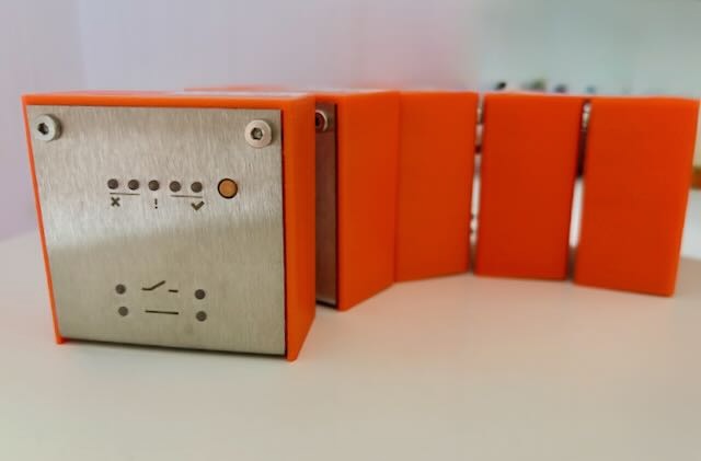
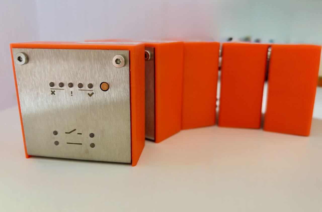
I designed and built a fencing weapon tester called ProTip.
If you want to purchase a ProTip tester, please click here.
Electronic scoring systems for fencing use wires (called body wires) that lead from the weapon through the athlete’s sleeve down to a spring-loaded wire spool that connects at their waist and links them to the central box.
Fencing swords are essentially a switch that closes (or opens, depending on the weapon) when it touches the opponent. Fencers need to ensure that their equipment is working properly and many use a weapon tester that indicates continuity whilst making adjustments. Unfortunately these testers, which are basically just a battery and light, don’t tell the whole story about how a weapon is working.
Whilst preparing for competitions, I have spotted high resistance in my epees which indicated pinched wires at the socket that were about to fail, dirty tips, badly adjusted contact springs inside the tip (meaning that only pressure aligned to the end of the point caused the tip to operate correctly), dirty contacts inside the guard sockets, and a faulty body wire where the screw terminals were loose. The fine wires in the blade can become damaged, and break the circuit when the sword is beat against another, and the switch in the tip can become dirty which prevents points from being detected properly. Both these faults appear as high resistance through the weapon, which offers an opportunity to spot them before they affect performance. All of these faults were not obvious when normally using my kit, but all of them can and do cause points to not register which is a big problem when every point counts.
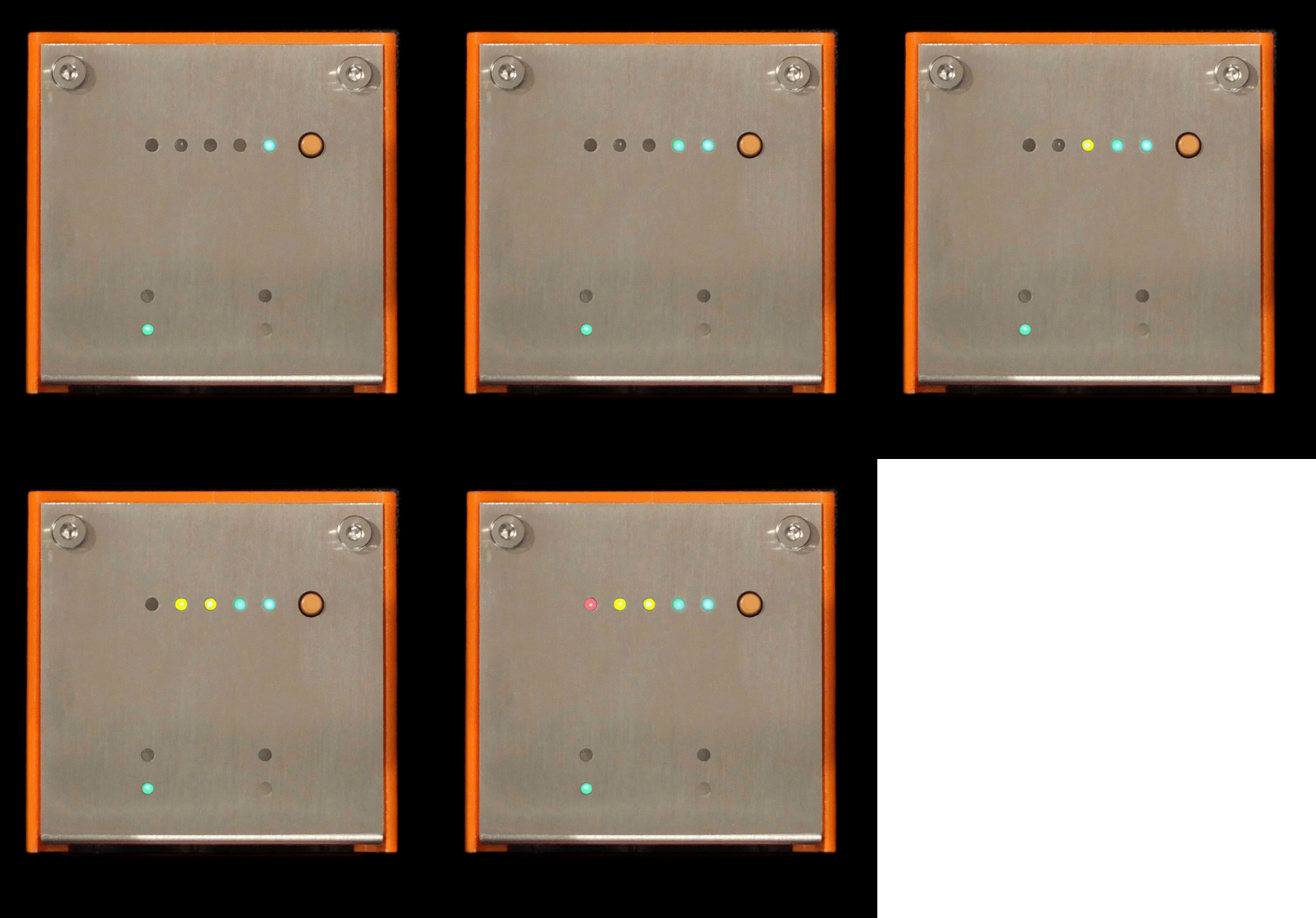
My tester measures resistance through the weapon and indicates this using a row of LEDs to show low (which passes the tests that are carried out at large competitions), marginal, and high (which would definitely fail at a competition, and can cause hits to not register). There is also indication of intermittent breaks, which can cause annoying interruptions at foil (which has a normally closed switch), and missed points at epee.
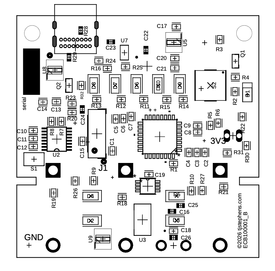
The tester is built around a constant current source that passes a known current through the weapon. The small voltage that arises from the resistance in the weapon is amplified and then detected using the ADC input on an STM32 microcontroller. The microcontroller reads the voltage, converts to resistance and then displays the measurement on the LED row. When an intermittent drop-out is detected, the intermittent light is turned on briefly.
The software running on the microcontroller is a simple state machine where a loop runs to keep the interface updated and service the button inputs to switch modes or switch the device off. In the background, the ADC is read into a buffer using DMA and an interrupt fires when the buffer fills up to trigger averaging and data processing. The microcontroller features a built-in temperature sensor, so I’m using this to correct the resistance measurement for the effects of temperature and ensure a consistent measurement. Without compensation, the resistance measurement can vary by somewhere in the region of 0.5ohms which is a large enough difference to erroneously indicate that a weapon passes the tests when it should not. The correction algorithm is able to reduce this error to less than 0.05ohms over the operating temperature range of 5-40°C, which is more than good enough for the use case.
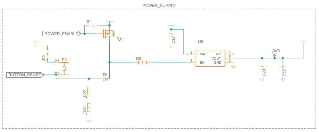
Power is controlled using a LDO regulator that has an enable pin. When this pin is not pulled high, the regulator sits in a very low power state that draws less than 1uA, which is essentially zero compared with the capacity of the LiPo battery in the tester. When the user presses the button, the gate of a P-channel FET is pulled low. The FET turns on the enable pin of the regulator and energises the supply line for the system. This causes the microcontroller to boot, whereupon it sets a GPIO to continue to hold the FET on. A watchdog timer in the microcontroller is used to wait for 3 minutes of inactivity and then reset the GPIO and turn the system off. This means that I can have a soft power function and not require a latching power switch, which simplifies the interface. At power on, the device reads the battery voltage with another ADC channel and reports the measurement on the LED row.
A USB C connector on the back face lets the user charge the battery in a couple of hours, and power usage is low enough that there’s at least 50hours of active use per charge. This is equivalent to testing hundreds (or maybe thousands) of weapons since the lights are only lit for a few seconds for each test.
Mechanically, the tester is based on a 3d printed enclosure with a stainless steel front plate. I connected the front plate to the test circuit so that users can test their body wires, and resistance through the guards of their weapons (quantities that must also be checked) without additional cables or accessories. I fit light guides to link the LEDs on the PCB to the front plate and improve their visibility. Because the system is tough plastic and metal, it will survive in a fencers bag, which is an unforgiving environment full of sweaty kit, weapons, and a heavy fencing mask. I also apply conformal coating to the PCB to further protect the main circuit from moisture should a water bottle leak or the bag get caught in the rain. The case is tough enough that the tester doesn’t need a carry case to protect it and the simple interface isn’t fragile like a touch screen or LCD display.
To make sure that the tester is safe to use, I checked it against IEC EN61010-1, which is the electrical safety standard for test equipment. The standard lists a series of tests that need to be completed, and calculations that show that the device is safe. The enclosure passes drop tests, and impact tests where a 10J impulse is applied through a cylindrical mass. The electrical safety is verified by considering fault conditions and ensuring that there are no unsafe temperature rises as a result of these. I also confirmed that the battery I’ve chosen is fully protected against short circuit and over-charging (both tests that were slightly nerve-wracking to perform and needed fire protection nearby).
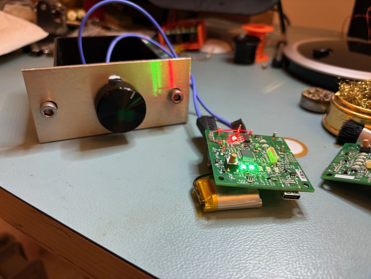
To ensure that there were no ill effects caused by electrical interference, I scanned the electromagnetic radiation emitted whilst the device was operating in a TEM cell using a spectrum analyser. There are no frequencies in the test range that exceed, or even come close to the limits in IEC 61000-6-4 and 61000-6-2.
This tester is a bit of a labour of love, but it’s something that I really think is missing from the market right now. There are lots of simple testers that show only continuity, and there are some expensive, complicated units targeted at armourers that can make more detailed measurements of resistance but there’s nothing aimed at fencers who simply want a GO/NOGO indication before or during a competition. I sell the tester at my website