Automated heating control
As part of my distributed temperature sensing network, I built a system to control the central heating. The basis of the board is an ESP8266-12 radio with integrated micro-controller. This controls a relay which allows the heating control to be toggled, and includes a pair of Maxim DS18b20 temperature sensors to monitor the heating flow and return water temperatures.
Hardware
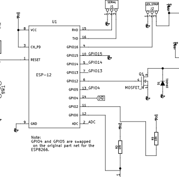
At its most basic, the circuit is an ESP8266 wifi microcontroller that switches a relay. My insiration was a blog-post I read by Hristo Borisov, where he mentioned using Hi-Link mains power supplies to get 5v/3.3v from the mains. This lead me to realise that this would be an ideal way to power a small project that needs to be permanently powered on.
I designed a PCB in KiCAD that includes a mains PSU to 5V, a 3v3 regulator to produce usable power for the ESP8266. I’m using a 5v power supply because there are no relays that I could find which operate on 3v3, whereas there are several Coto 5v reed relays listed on the various electronics distributors sites. I switch the power to the relay with a JFET that’s driven from a GPIO line on the ESP8266.
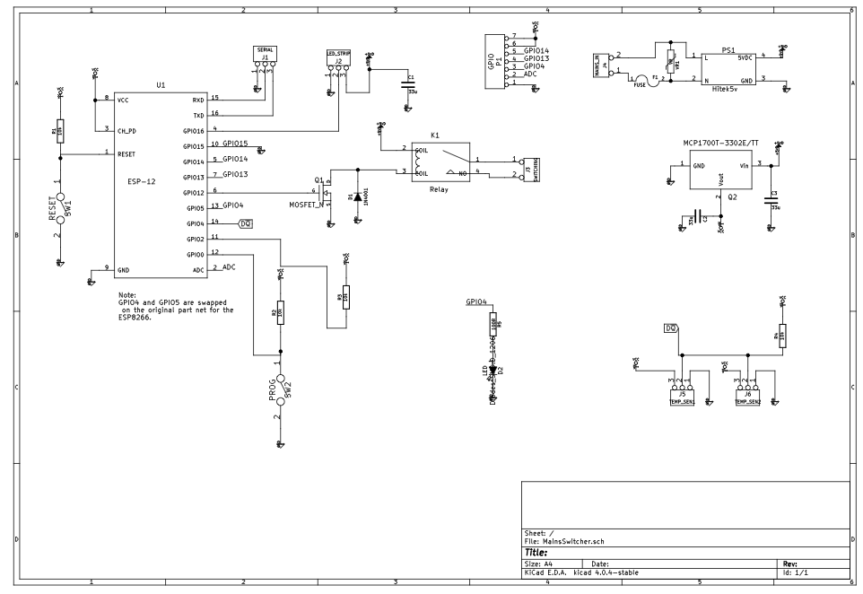
The temperature sensors are the popular DS18b20 one-wire sensors that require a single data line, plus power and ground.
Since I knew that there would be other applications for this board, I broke out all of the spare GPIO lines to headers, and included a 5v and 3v3 pin to enable as many things as possible to be connected.
There’s a large isolation slot to protect the low voltage part of the PCB from the mains secion, in addiiton to a fuse to catch things if they go wrong (not least because the temperature sensors will be connected directly to the water pipes in the house).
Software
I used the PubSubClient MQTT library to conduct messaging back to a Raspberry Pi home server that I keep running to monitor things around the house. There’s a basic setup page that I cobbled together to allow the system to set the WiFi SSID and password (it starts an access point if it fails to connect to a known network after a few minutes of powering on).
The code itself runs a loop that has it reporting the temperature of each sensor every few seconds because the boiler sometimes has a habit of overheating. I monitor the temperature and if it gets close to the overheat temperature, I cut the heating (via a workflow in NodeRed on the Raspberry Pi). If a message arrives to turn the heating on or off, I switch the relay which is connected in series with the timeclock line on the boiler, which calls for heat. In this way, there is the fallback on the built-in timer should I need to deactivate the system.
Packaging
Everything is packaged in an 80x80 junction box, which is secured in the cupboard under the boiler in the kitchen. This makes it easily accessible and ensures that the whole system is as unobtrusive as possible.
Control
The system is controlled with a large NodeRed flow that takes input from a series of timers (to provide operation at the correct times of day, the temperature sensors, and manual controls).
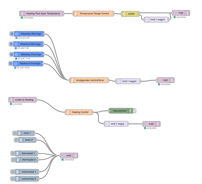
This system is easily extensible to add extra thermostats as the temperature sensor network grows, for instance to include awareness of the weather forecast, or the temperature in a specific room in the house. Another feature that can be added is integration with a webservice like IFTTT, which allows geolocation and can automatically call the heating to turn on when you leave work.