Wearable Computing
Wearable computing is all the rage at the moment , and I was recently given a face-mounted miniature display unit. I was advised that it was faulty and had never worked, but it was too interesting to pass up the chance to look at it.
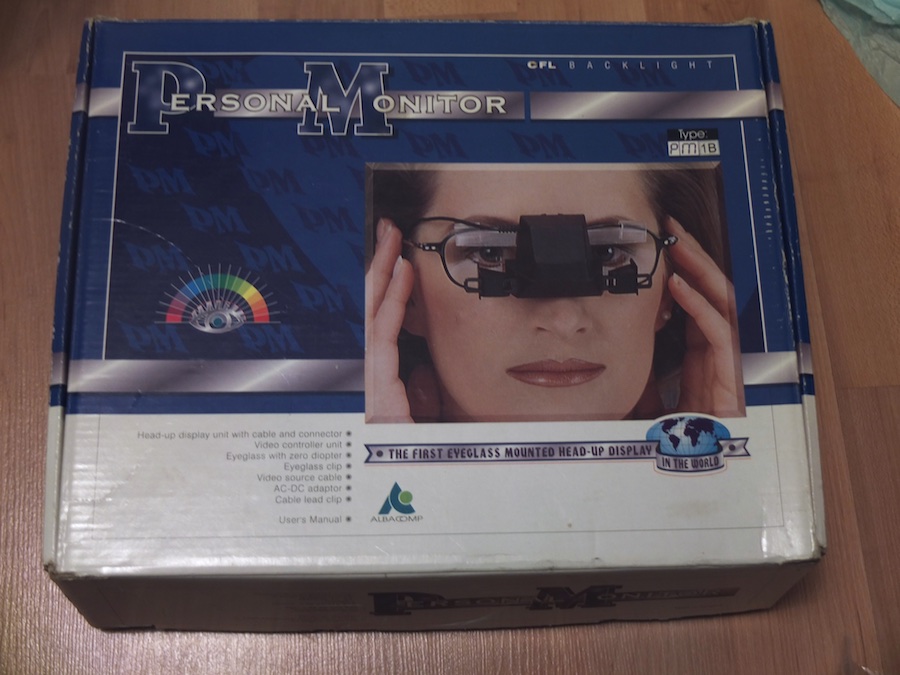
The display contains a miniature LCD screen with a CFL backlight (the same as was in laptops until LEDs replaced those in the last couple of years to 2015). In front of the screen is a beamsplitter, and some lenses to allow your eyes to focus on the screen right in front of them. Finally, there are a couple of miniature mirrors on arms to direct the picture into your eyes.
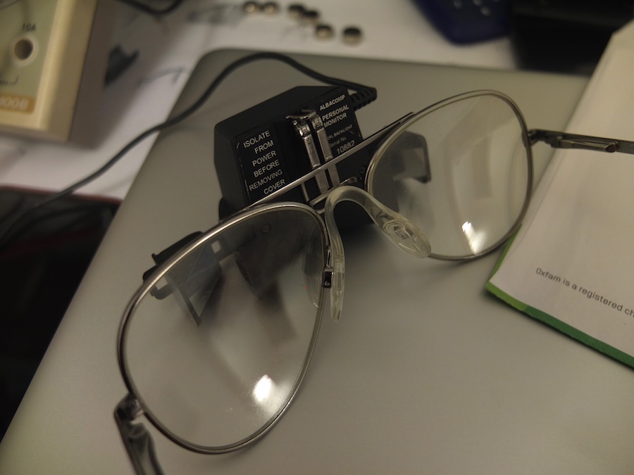
The display is old enough that it’s only about 320 lines resolution (i.e. half-VGA), and it has a composite video input. I was initially unsure what I’d be able to do to test it since we don’t have a huge amount of old video hardware around the house, until a friend at OxHack reminded me that Raspberry Pi computers have a composite video output. Knowing this, it’s obvious that this display has to be made to work.
Getting it to Work
The display came to me with a wall-wart power supply, but I found that it did absolutely nothing when powered on. The first rule of electronics trouble-shooting is to look for burnt things, but the board looked clean and nothing was obviously faulty. The second rule of electronic trouble-shooting is to measure voltages, so I got my multimeter out and started probing.
The board has a number of test-points on it, which are labelled with voltages so I probed those first. All of them read 12V, which is the supply voltage of the wall-wart, despite some being labelled as 5V and 13V. My immediate suspicion was that a capacitor in a power supply on the board was faulty – the thinking being that there was likely a switch-mode supply to generate the various working voltages, and these will contain decoupling capacitors to quieten the electrical noise that they generate.
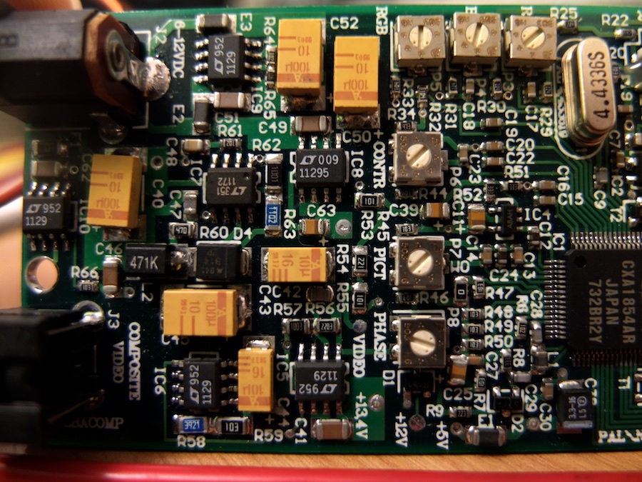
I probed a bunch of places on the board, and tested many of the capacitors that I could find, but everything seemed to be working. There was also no continuity between ground and the power in pin, which suggested that wasn’t a cause either. Next thing to look at was the power supply chips. There are a number of LT1129 LDO regulators on the board, and a datasheet was simple to find. I checked the pinout and started testing the voltages there. Almost the first thing I noticed when I probed the chip is that the input voltage was not the same as the voltage reading on the input pin, and that the ground pin was at 12V!
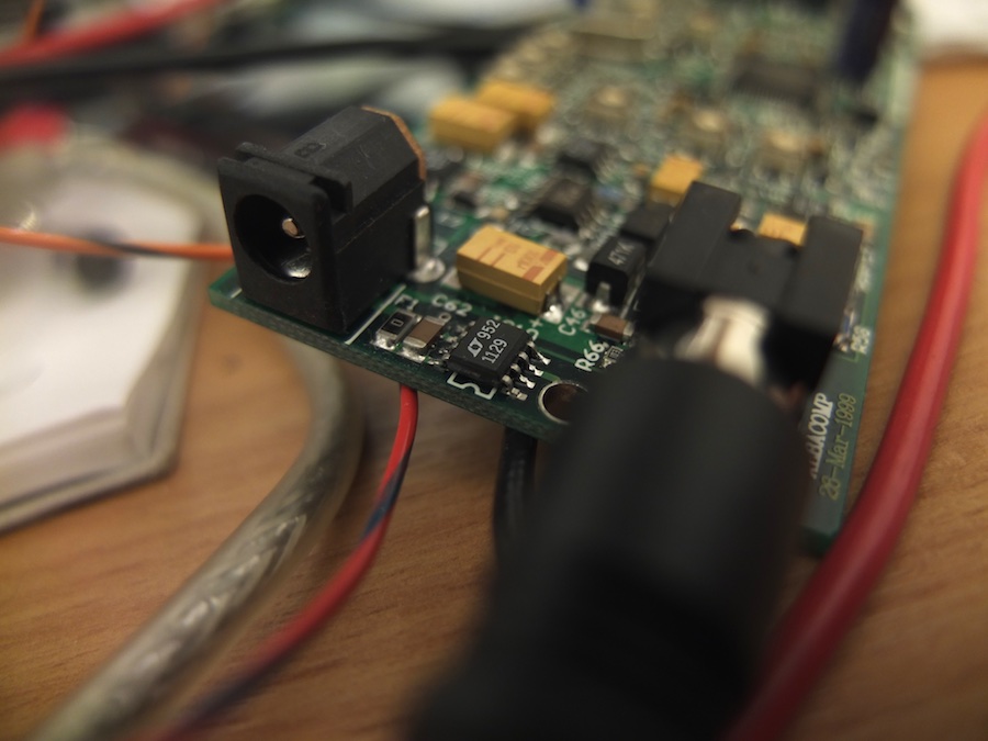
The ‘fault’ in this device is not a fault at all: it’s simply that the PSU is of the wrong polarity and was therefore connected backwards. Simply swapping the terminals (by cutting the cable and reversing the polarity) has fixed this little display.
Wearable Computing

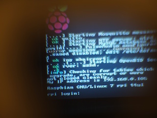
With the display working, I connected it up to one of my Raspberry Pis and got to enjoy the wearable computing revolution for myself. Two adjustments are required in the Pi for this to be more usable with the low-resolution display. In /boot/config.txt (which is also the DOS-readable partition of the SD card), I changed the following lines to read:
sdtv_mode=2
framebuffer_width: 320
framebuffer_height: 240
This is not yet a fully useful mobile computing experience on ccount of the lack of a suitable power source to supply the somewhat immodest demands of the Raspberry Pi and display together, but I think that this has promise and look forward to developing it further.